IPSEC VPN and NAT-T (Fortigate and Cisco)
Today's writing will be about IPSec configuration when tunnel endpoints are located behind NAT. Let's explain the challenges we need to overcome when a tunnel endpoint is behind NAT.
IPSec provides confidentiality, authenticity and integrity. A NAT device alters the source IP adress, so the remote endpoint will fail to match the source IP address. Authentication check will fail because of this alteration. Which also means integrity check will fail also as the original packet was altered in the middle. As the payload is encrypted the NAT device cannot also change anything in encrypted portion of the IP header.
NAT-Traversal comes in rescue in such cases. With NAT-T, an extra UDP header is added which encapsulates the IPSec ESP header. As this new UDP header is not encrypted, the NAT device can now make the necessary modifications to the packet, so that encrypted packets can reach to the tunnel endpoint. And finally to the end hosts in the network.
During IKE phase, both IPSec peer will negotiate that they are using NAT-T. After this negotiation, traffic flow switches to port 4500 over UDP. When traffic flows switches to UDP/4500, it means IPSec is using NAT-T.
With NAT-T, we need to take care of the following protocol/ports if there is any firewall between the IPSec peers - IP protocol 50 (ESP), UDP/500 (IKE) and UDP/4500 (NAT-T).
Lets implement this in a lab scenario. Here comes our test network -
Lets implement this in a lab scenario. Here comes our test network -
Network Topology
 |
| IPSec VPN with NAT-T |
We have two sites A and B. On site A, we have a Fortinet firewall which is the IPSec peer, DHCP server and gateway for the network. On site B, we have a Cisco router which functions as gateway for the site and also does the NAT duties. The we have a Fortinet firewall which functions as a VPN peer. The tunnel will be established between Fortinet firewalls and the PAT router will be configured to allow this network setup.
VPN-GW-Site-A
The interfaces are configured as follows -
 |
| Interface Configuration |
Here the Fortigate firewall has two interfaces configured and the interfaces are put into two different zones. The zones are named LAN-Zone and WAN-Zone which is self-explanatory and will be used to show zone based firewall configuration in Fortigate. And "port1" is the management port.
 |
| IKE (Phase 1) Configuration |
 |
| IPSec (Phase 2) Configuration |
Firewall rules are configured as follows -
 |
| Firewall Policies |
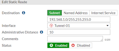
Now comes the routing part. We need to divert traffic towards network 192.168.1.0/24 through the tunnel which is archived by using static route.
 |
| Static Route |
VPN-Gateway-Site-A # get router info routing-table details
Routing table for VRF=0
Codes: K - kernel, C - connected, S - static, R - RIP, B - BGP
* - candidate default
S* 0.0.0.0/0 [10/0] via 10.10.50.1, port2
C 10.10.50.0/24 is directly connected, port2
S 192.168.1.0/24 [10/0] is directly connected, Tunnel-01
C 192.168.2.0/24 is directly connected, port4
C 192.168.199.0/24 is directly connected, port1
This completes the configuration of the "VPN-SW-Site-A" - Fortigate firewall which is the tunnel endpoint in Site A.
VPN-GW-Site-B
Here the configuration is exactly the same apart from some changes in IP addressing.
The interfaces are configured as follows -
 |
| Interface Configuration |
 |
| IKE (Phase 1) Configuration |
IKE phase is configured as picture above. The important thing is enabling "NAT Traversal". Again, NAT-T must be enabled on both sides. Here the remote gateway is the Fortigate unit in Site A - VPN-GW-Site-A (10.10.50.2/24).
And the IPSec phase is configured as the picture below which is exactly same as Site A with difference in IP address configuration only.
 |
| IPSec (Phase 2) Configuration |
 |
| Firewall Policies |
 |
| Static Route |
Routing table for VRF=0
Codes: K - kernel, C - connected, S - static, R - RIP, B - BGP
O - OSPF, IA - OSPF inter area
N1 - OSPF NSSA external type 1, N2 - OSPF NSSA external type 2
E1 - OSPF external type 1, E2 - OSPF external type 2
i - IS-IS, L1 - IS-IS level-1, L2 - IS-IS level-2, ia - IS-IS inter area
* - candidate default
S* 0.0.0.0/0 [10/0] via 172.16.1.1, port2
C 172.16.1.0/24 is directly connected, port2
C 192.168.1.0/24 is directly connected, port4
S 192.168.2.0/24 [10/0] is directly connected, Tunnel-01
C 192.168.199.0/24 is directly connected, port1
PAT-Ro-Site-B
The router has the following configuration for it's interfaces -
interface GigabitEthernet0/0
ip address 10.10.50.1 255.255.255.0
interface GigabitEthernet0/1
ip address 172.16.1.1 255.255.255.0
Routing table of the router is given below -
PAT-Router#sh ip route
Gateway of last resort is not set
10.0.0.0/8 is variably subnetted, 2 subnets, 2 masks
C 10.10.50.0/24 is directly connected, GigabitEthernet0/0
L 10.10.50.1/32 is directly connected, GigabitEthernet0/0
172.16.0.0/16 is variably subnetted, 2 subnets, 2 masks
C 172.16.1.0/24 is directly connected, GigabitEthernet0/1
L 172.16.1.1/32 is directly connected, GigabitEthernet0/1
The router is performing source NAT (S-NAT) for the network 192.168.1.0/24 (refer to the network diagram). GE0/0 is the outside interface and GE0/1 is the inside interface for NAT.
interface GigabitEthernet0/0
ip nat outside
interface GigabitEthernet0/1
ip nat inside
ip access-list standard Inside-Nat-Pool
permit 192.168.1.0 0.0.0.255
ip nat source list Inside-Nat-Pool interface GigabitEthernet0/0 overload
This router also does port forwarding (UDP/500, UDP/4500) to internal Fortigate - VPN-GW-Site-B. So, by means of port forwarding, IPSec traffic will be forwarded to the Fortigate. As NAT-T is enabled on both Fortigate units, it is possible to encrypt and decrypt traffic at both ends of the tunnel. Port forwarding is also known as destination NAT (D-NAT).
ip nat inside source static udp 172.16.1.2 500 interface GigabitEthernet0/0 500
ip nat inside source static udp 172.16.1.2 4500 interface GigabitEthernet0/0 4500
Verification and troubleshooting
We run ping from PC-Site-B (192.168.1.101/24) to PC-Site-A (192.168.2.101/24).
PC-Site-B> ping 192.168.2.101
84 bytes from 192.168.2.101 icmp_seq=1 ttl=62 time=2.077 ms
84 bytes from 192.168.2.101 icmp_seq=2 ttl=62 time=1.816 ms
84 bytes from 192.168.2.101 icmp_seq=3 ttl=62 time=1.830 ms
84 bytes from 192.168.2.101 icmp_seq=4 ttl=62 time=1.785 ms
At the same time we run packet capture on both the Fortigate firewalls with the following command -
diagnose sniffer packet any 'udp and (port 500 or port 4500)'
Also, we are debugging NAT translations in our Cisco router. All the debugging are executing at the same time.
In VPN-GW-Site-B, we capture the the following -
4.781772 172.16.1.2.4500 -> 10.10.50.2.4500: udp 1
Which means that VPN-GW-Site-B (VPN-GW-Site-B) is trying to make a connection with VPN-GW-Site-A (VPN-GW-Site-B) over UDP/4500 port.
In PAT-Ro-Site-B we observe -
PAT-Ro-Site-B# debug ip nat
*Aug 27 22:54:17.977: NAT*: s=172.16.1.2->10.10.50.1, d=10.10.50.2 [13970]
Which confirms that traffic is source NATed.
In VPN-GW-Site-A we see the following -
8.144105 10.10.50.1.4500 -> 10.10.50.2.4500: udp 1
The return traffic over UDP/4500 will flow in the opposite direction, in PAT-Ro-Site-B, we will see that traffic is destination NATed.
PAT-Ro-Site-B# debug ip nat
*Aug 27 22:54:17.844: NAT*: s=10.10.50.2, d=10.10.50.1->172.16.1.2 [4728]
The NAT table in the Cisco router looks like this -
PAT-Ro-Site-B#sh ip nat translations
Pro Inside global Inside local Outside local Outside global
udp 10.10.50.1:500 172.16.1.2:500 --- ---
udp 10.10.50.1:4500 172.16.1.2:4500 10.10.50.2:4500 10.10.50.2:4500
udp 10.10.50.1:4500 172.16.1.2:4500 --- ---
This is the how IPSec with NAT-T works. For further IPSec troubleshooting have a look at IPSec Site-To-Site VPN between Fortigate and Cisco Router.
Final configuration can be downloaded from link - Configuration Download.
Further reading and reference -


Comments
Post a Comment