DHCP Option 82 in ISP network - Customer IP assignment (DHCP Snooping & IP Source Guard) with Cisco IOS
The other day; I was testing how my ISP is protecting itself from customer exploitation. Normally I directly connect my router to the network cable provided by ISP. This time around I have connected a switch to the network cable from the ISP. Then I have configured the switch port (ISP connection) to an access VLAN and also configured 2 other switch ports to the same vlan. Then I have connected 2 routers and expecting they will be assigned 2 IP addresses (1 for each router). To my surprise only one of the router was getting dynamically assigned IP adress from the ISP. The second router was not getting any IP adress at all. I even went further to set an static IP adress (from ISP network) to the second router. Another surprise - even with static IP assignment, that router could not even ping the ISP's gateway. That got me thinking - how the ISP is protecting itself from such customer exploitation in the first place.
Disclaimer - This is just a story to show the readers how the technical things are implemented in the ISP network. Be respectful to yours ISP's terms of usage.
Topology
Let's show our network topology. A picture is always better than thousand words -
Everything that is prefixed with "P" is the ISP/Provider part of the network which is not visible to the customer/end-user. And everything prefixed with "C" is the customer/end-user part of the network which is not visible to the provider/ISP.
All the network devices are Cisco IOS routers/switches, DHCP server is Microsoft Windows server and customer pc's are linux based client.
In Customer Network - they have configured C_VLAN - 501 and configured port Gi0/1, Gi1/2 and Gi1/3 in "C_SW" to be access ports of vlan id 501 (untagged vlan).
In Provider Network - they have configured P_VLAN - 101 - 10.10.101.0/24. In "P_SW" port Gi0/1 is access port in vlan 101 (untagged) towards customer; port Gi0/0 is uplink/trunk port (tagged) towards provider gateway. "P_RO" is the gateway for the network - 10.10.101.0/24 (customer's local gateway). And "P_DHCP" is the DHCP server responsible for allocating IP adress from network 10.10.101.0/24 to different customers.
Configuration
Our configuration has 3 parts - customer devices, provider devices and provider DHCP server.
Customer Switch and Routers
We have configured; "C_SW" as follows -
C_SW#
vlan 501
name Internet
!
interface Gi0/1 -- ISP Connection
switchport access vlan 501
switchport mode access
spanning-tree portfast edge
!
interface Gi1/2 -- Customer Device
switchport access vlan 501
switchport mode access
spanning-tree portfast edge
!
interface Gi1/3 -- Customer Device
switchport access vlan 501
switchport mode access
spanning-tree portfast edge
!
We will take the ISP connection in port Gi0/1 of the switch and will connect two linux client to port Gi1/2 and Gi1/3. Just a simple vlan configuration to connect multiple hosts towards the ISP.
Our linux clients will be configured either as DHCP client or use static IP assignment.
C_PC01:~# cat /etc/network/interfaces
# The primary network interface
allow-hotplug ens3
iface ens3 inet static
address 10.10.101.99/24
netmask 255.255.255.0
gateway 10.10.101.1
dns-nameservers 10.10.101.1
C_PC02:~# cat /etc/network/interfaces
# The primary network interface
allow-hotplug ens3
iface ens3 inet dhcp
Provider Switch and Router
We have configured; "P_RO" as follows -
P_RO#
interface GigabitEthernet0/0
no ip address
no shutdown
!
!!! P_SW facing vlan interface
!!! DHCP helper configured towards the actual DHCP server
!!! DHCP helper configured towards the actual DHCP server
interface GigabitEthernet0/0.101
encapsulation dot1Q 101
ip address 10.10.101.1 255.255.255.0
ip helper-address 192.168.199.91
no shutdown
!
!!! DHCP server facing interface
interface GigabitEthernet0/1
ip address 192.168.199.138 255.255.255.0
no shutdown
!
!!! P_SW will insert DHCP option 82 with empty GIADDR
!!! Router will trust DHCP packet with empty GIADDR which has option 82 set
ip dhcp relay information trust-all
!
Now the P_SW configuration; this is where all the ISP protection happens. We will configure DHCP snooping in the switch, customer facing ports will be untrusted for DHCP snooping. The snooping will insert option 82 in the DHCP packets originated from the customer. We will customize "circuit-id" field of option 82 which is sent with the following format "%hostname:%portname". Also have customized the "remote-id" field of option 82 which is sent as "%hostname". So, our remote-id will be - P_SW and circuit-id will be - P_SW:Gi0/1. The DHCP server will not allocate IP adress to customer device's MAC-address. Instead the DHCP server will allocate IP adress to the customer using the circuit-id field of option 82 in the DHCP packet. As circuit-id is bound to the switch's interface/port number; a customer will only be assigned one single dynamic IP adress. We will also configure IP Source Guard in customer facing port so that only customer hosts which has dynamically assigned IP adress from provider's DHCP server is allowed into the network. Static IP assigned customer device is not permitted because of IP source guard. Remember IP source guard only works when DHCP snooping is already configured.
P_SW#
!
vlan 101
name Customer
!
ip dhcp snooping
!!! DHCP snooping for customer vlan 101
ip dhcp snooping vlan 101
!!! Changing option 82 remote-id field to switch's hostname
ip dhcp snooping information option format remote-id hostname
!
interface Gi0/0
switchport trunk allowed vlan 101
switchport mode trunk
spanning-tree portfast trunk
!!! P_RO facing interface which is trusted for DHCP snooping
ip dhcp snooping trust
!
!!! C_SW facing interface which is untrusted for DHCP snooping
interface Gi0/1
switchport access vlan 101
switchport mode access
spanning-tree portfast
!!! Changing circuit-id field of option 82 to switch's hostname:interfacename
ip dhcp snooping vlan 101 information option format-type circuit-id string P_SW:Gi0/1
!!! Configures IP source guard so only DHCP clients are allowed through the port
ip verify source
!
Provider DHCP Server Configuration
We are using Microsoft Windows server as provider's DHCP server. With Windows DHCP we can create policies in which can use different field's of option 82.
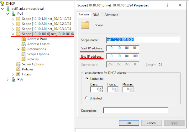
Our DHCP scope is configured with 10.10.101.0/24 with a range 10.10.101.101 - 200; Router and DNS IP - 10.10.101.1.
02 - DHCP Scope Configuration
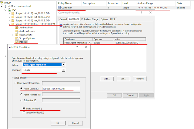
Now we will configure a DHCP policy as below -
03 - DHCP Policy Configuration
Our DHCP policy works as follow; the P_RO sends the DHCP packet to the DHCP server which contains the DHCP option 82 with circuit-id and remote-id field. The policy will match if the circuit-id contains the value P_SW:Gi0/1 which equals to 505f53573a4769302f31 in hexadecimal; we will allocate an IP adress from the range 10.10.101.191-200. Windows server supports only matching option 82 field values in hex format.
Testing
Now it is time to test everything works as it should be. Here we are expecting - C_PC01 will get an IP adress from the range defined in DHCP policy and under no circumstances the customer will be allocated more than one IP adress. And C_PC02 will not be allowed to communicate to ISP network if it is using static IP adress assignment.
Let's make a DHCP adress request from C_PC01 -
CPC01:~# dhclient -v -d -nw ens3
Internet Systems Consortium DHCP Client 4.4.1
Copyright 2004-2018 Internet Systems Consortium.
All rights reserved.
For info, please visit https://www.isc.org/software/dhcp/
Listening on LPF/ens3/50:ff:53:00:06:00
Sending on LPF/ens3/50:ff:53:00:06:00
Sending on Socket/fallback
DHCPDISCOVER on ens3 to 255.255.255.255 port 67 interval 8
DHCPOFFER of 10.10.101.191 from 10.10.101.1
DHCPREQUEST for 10.10.101.191 on ens3 to 255.255.255.255 port 67
DHCPACK of 10.10.101.191 from 10.10.101.1
bound to 10.10.101.191 -- renewal in 41858 seconds.
We can see that we are allocated IP adress (10.10.101.191) from the DHCP range defined under policy which shows that our DHCP policy is working.
If we capture packet in the P_RO's Gi0/0 interface we will see that P_SW is inserting option 82 with the values we have set for circuit-id and remote-id. A full capture of the 4 DHCP packets is given in the references section.
04 - DHCP Packet Capture
We can verify the DHCP snooping and IP source guard operation from the P_SW using commands below -
P_SW#show ip dhcp snooping
Switch DHCP snooping is enabled
Switch DHCP gleaning is disabled
DHCP snooping is configured on following VLANs:
101
DHCP snooping is operational on following VLANs:
101
Insertion of option 82 is enabled
circuit-id default format: vlan-mod-port
remote-id: P_SW (hostname)
Option 82 on untrusted port is not allowed
Verification of hwaddr field is enabled
Verification of giaddr field is enabled
DHCP snooping trust/rate is configured on the following Interfaces:
Interface Trusted Allow option Rate limit (pps)
----------------------- ------- ------------ ----------------
GigabitEthernet0/0 yes yes unlimited
Interface Trusted Allow option Rate limit (pps)
----------------------- ------- ------------ ----------------
Custom circuit-ids:
GigabitEthernet0/1 no no unlimited
Custom circuit-ids:
VLAN 101: P_SW:Gi0/1
P_SW#show ip dhcp snooping binding
MacAddress IpAddress Lease(sec) Type VLAN Interface
------------------ --------------- ---------- ------------- ---- --------------------
50:FF:53:00:06:00 10.10.101.191 85918 dhcp-snooping 101 GigabitEthernet0/1
Total number of bindings: 1
P_SW#show ip source binding
MacAddress IpAddress Lease(sec) Type VLAN Interface
------------------ --------------- ---------- ------------- ---- --------------------
50:FF:53:00:06:00 10.10.101.191 85908 dhcp-snooping 101 GigabitEthernet0/1
Total number of bindings: 1
Now if we try to set an static IP in C_PC02 and try to ping the ISP gateway (10.10.101.1) and here our expectation is that ping will fail.
CPC02:~# ip addr
2: ens3: <BROADCAST,MULTICAST,UP,LOWER_UP> mtu 1500 qdisc pfifo_fast state UP group default qlen 1000
link/ether 50:57:ae:00:08:00 brd ff:ff:ff:ff:ff:ff
altname enp0s3
inet 10.10.101.99/24 brd 10.10.101.255 scope global ens3
valid_lft forever preferred_lft forever
inet6 fe80::5257:aeff:fe00:800/64 scope link
valid_lft forever preferred_lft forever
CPC02:~# ping 10.10.101.1
PING 10.10.101.1 (10.10.101.1) 56(84) bytes of data.
--- 10.10.101.1 ping statistics ---
5 packets transmitted, 0 received, 100% packet loss, time 8179ms
Now the reader's have an idea how an ISP allocates IP addresses for the customer at the same time preventing IP address exploitation from the customer.


Comments
Post a Comment