Mixing layer-3 and layer-2 over a single aggregated link? Possible???
I have tried a strange combination recently and was very surprised to see that it works - mixing layer-2 and layer-3 over an LACP aggregated interface. I have no explanation why it works. Does any of my reader have any idea?
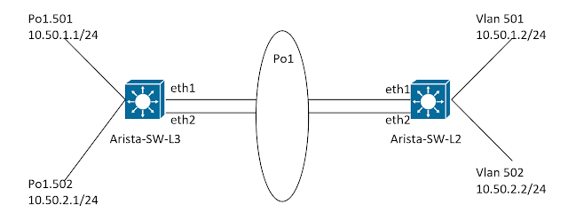
Let's introduce our topology first-
 |
| Fig 01 - Link-aggregation Topology |
We are using two Arista switches. In Arista-SW-L3 we will create a L3 (layer 3) link-aggregation and in Arista-SW-L2 we will create a L2 (layer 2) link-aggregation over the same pair of interfaces (eth1 and eth2). Then we will verify the connectivity by doing ping from the L2 side (vlan interfaces) to the L3 side (port-channel interfaces). And come to conclusion that we can mix and match L2 and L3 over a single link-aggregation interface.
Let's configure the L3 side of our aggregated link -
Arista-SW-L3 configuration
We configure the switch by running the following commands -
interface Ethernet1
no switchport --Creating L3 port
channel-group 1 mode active --Enabling link-aggregation with LACP
!
interface Ethernet2
no switchport
channel-group 1 mode active
!
interface Port-Channel1
no switchport
!
interface Port-Channel1.501
encapsulation dot1q vlan 501 --Enable a L3 interface which can process frames with VLAN id 501
ip address 10.50.1.1/24
!
interface Port-Channel1.502
encapsulation dot1q vlan 502
ip address 10.50.2.1/24
!
Now we will configure the L2 side of our aggregated link -
Arista-SW-L2 configuration
We configure the switch by running the following commands -
vlan 501-502
!
interface Vlan501
ip address 10.50.1.2/23
!
interface Vlan502
ip address 10.50.2.2/23
!
interface Ethernet1
channel-group 1 mode active
!
interface Ethernet2
channel-group 1 mode active
!
interface Port-Channel1
switchport mode trunk --Aggregated interface works at L2 only
switchport trunk allowed vlan 501-502 --Allowing VLAN 501 and 502 over L2 aggregated trunk
!
Verification
From our L3 switch we can verify our port-channel 1 interface is not enabled for spanning tree, hence it is a L3 interface.
Arista-SW-L3#sh spanning-tree
MST0
Spanning tree enabled protocol mstp
Root ID Priority 32768
Address 5000.00cb.38c2
This bridge is the root
Bridge ID Priority 32768 (priority 32768 sys-id-ext 0)
Address 5000.00cb.38c2
Hello Time 2.000 sec Max Age 20 sec Forward Delay 15 sec
Interface Role State Cost Prio.Nbr Type
---------------- ---------- ---------- --------- -------- --------------------
--No interface is running spanning tree
We can also verify our aggregated interface is a L3 interface by running commands below -
Arista-SW-L3#sh int status
Port Name Status Vlan Duplex Speed Type Flags Encapsulation
Et1 connected in Po1 full unconf EbraTestPhyPort
Et2 connected in Po1 full unconf EbraTestPhyPort
Po1 connected routed full unconf N/A --L3 interface
Po1.501 connected routed full unconf dot1q-encapsulation 501 --L3 interface
Po1.502 connected routed full unconf dot1q-encapsulation 502 --L3 interface
Arista-SW-L3#sh ip int brief
Interface IP Address Status Protocol
Port-Channel1 unassigned up up
Port-Channel1.501 10.50.1.1/24 up up
Port-Channel1.502 10.50.2.1/24 up up
Now we will look at the aggregated interface status in our L2 switch.
Arista-SW-L2#sh spanning-tree
MST0
Spanning tree enabled protocol mstp
Root ID Priority 32768
Address 5000.00d5.5dc0
This bridge is the root
Bridge ID Priority 32768 (priority 32768 sys-id-ext 0)
Address 5000.00d5.5dc0
Hello Time 2.000 sec Max Age 20 sec Forward Delay 15 sec
Interface Role State Cost Prio.Nbr Type
---------------- ---------- ---------- --------- -------- --------------------
Po1 designated forwarding 1999 128.100 P2p Edge --Interface is running spanning tree
Arista-SW-L2#sh int status
Port Status Vlan
Et1 connected in Po1
Et2 connected in Po1
Po1 connected trunk --Interface is a L2 trunk
Arista-SW-L2#sh ip int brief
Interface IP Address Status Protocol
Vlan501 10.50.1.2/23 up up
Vlan502 10.50.2.2/23 up up
Let's verify the connectivity by running a simple ping command from the L2 switch -
Arista-SW-L2#ping 10.50.1.1
PING 10.50.1.1 (10.50.1.1) 72(100) bytes of data.
80 bytes from 10.50.1.1: icmp_seq=1 ttl=64 time=21.3 ms
80 bytes from 10.50.1.1: icmp_seq=2 ttl=64 time=24.1 ms
80 bytes from 10.50.1.1: icmp_seq=3 ttl=64 time=21.2 ms
Arista-SW-L2#ping 10.50.2.1
PING 10.50.1.1 (10.50.2.1) 72(100) bytes of data.
80 bytes from 10.50.2.1: icmp_seq=3 ttl=64 time=20.2 ms
80 bytes from 10.50.2.1: icmp_seq=4 ttl=64 time=19.0 ms
80 bytes from 10.50.2.1: icmp_seq=5 ttl=64 time=18.1 ms
Arista-SW-L2#
Conclusion
So, it is now verified that we can have a working aggregated-link where one side is L3 and the other side is L2. But the question is why does it works. I don't have any explanation at the time of writing. I am guessing may be it is because on the L3 side of the link we are processing frames tagged with VLAN ids (501 and 502) by using the command "encapsulation dot1q vlan 501". May be one of my reader can give me some clues and explain it to me.


Interesting configuration. ICMP/PING are working fine but this if you transmit other packets that contain header and need to be serialised what will happen?
ReplyDeleteYou might try to transmit some diameter packet and take a tcp dump and see the packet travel is serialised or splitted. Just an idea.
For packet simulation you might use:
ReplyDeletehttp://packeth.sourceforge.net/packeth/Home.html