Stacking switches Part - III (Arista MLAG - Multi Chassis Link Aggregation)
Now it is time for the elephant in the room in the stacking series, which is called MLAG (multi chassis link aggregation). Vendors like Arista, Juniper, Extreme Networks, Cisco uses this as stacking method in their switches. Again this article is not a technical deep dive about MLAG, but rather looks at how it is configured in Arista switches.
Let's define our network constraints; the example has following characteristics -
- Two Arista switches will run peering between them and will form MLAG.
- Two Cisco test switches will form multichassis link-aggregation with Arista switches. They will simulate the client connection.
- From test switches, we will test connectivity by using a vlan interface over the link-aggregated interfaces.
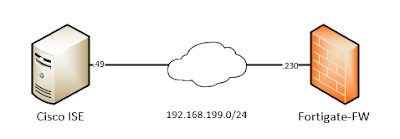
Our network topology looks like this -
 |
| Fig 01 - Arista MLAG Topology
Two Arista switches SW-U01 and SW-U02 will use interface eth6 and eth7 for forming MLAG peering. Then they will run LACP based link-aggregation with Cisco test switches over interface eth1 and eth2. The test switches - Test-SW-01 and Test-SW-02 will run a LACP based link-aggregation with Arista switches using their gi0/0 ang gi0/1 interfaces.
Between mlag switches we will select master-slave relationship using deterministic method. So,
SW-U01 - will be the master switch
SW-U02 - will be the slave switch
SW-U01 (master) configuration commands
For mlag peering traffic we need a VLAN and that VLAN will have a SVI (switched virtual interface). We will use VLAN 4094 for peering and 10.255.255.0/30 subnet for VLAN 4094 ip assignment.
Now we will create the peering VLAN, assign that VLAN to a trunk group named - Peering-Vlan, disable spanning tree on that VLAN, assign an IP address to the VLAN. Then we will create a link-aggregation interface over interfaces eth6 and eth7. The port channel needs to be layer-2 trunk port and allow peering VLAN.
vlan 4094
trunk group Peering-Vlan
no spanning-tree vlan 4094
interface Vlan4094
description Peering-Interface
ip address 10.255.255.1/30
interface Ethernet6
channel-group 2000 mode active
interface Ethernet7
channel-group 2000 mode active
interface Port-Channel2000
switchport mode trunk
switchport trunk group Peering-Vlan
Now comes the actual MLAG configuration - here domain-id is an arbitrary name which needs to be same on both switches. Priority command is and hidden command which sets SW-U01 as master switch. Other commands are pretty self-explanatory.
mlag
domain-id MLAG-SW-U01-SW-U02
local-interface Vlan4094
peer-address 10.255.255.2
primary-priority 1
peer-link Port-Channel2000
SW-U02 (slave) configuration commands
For SW-U02, the configuration commands are exactly same, just we will change the IP adress of the VLAN interface and peer switch IP address under mlag configuration. Also will omit the priority command as it is our slave switch.
vlan 4094
trunk group Peering-Vlan
no spanning-tree vlan 4094
interface Vlan4094
description Peering-Interface
ip address 10.255.255.2/30
interface Ethernet6
channel-group 2000 mode active
interface Ethernet7
channel-group 2000 mode active
interface Port-Channel2000
switchport mode trunk
switchport trunk group Peering-Vlan
mlag
domain-id MLAG-SW-U01-SW-U02
local-interface Vlan4094
peer-address 10.255.255.1
peer-link Port-Channel2000
At this point mlag peering should start working. If you are interested in verification and troubleshooting, skip to that section. I will go to that after presenting the configuration of the test switches.
Test-SW-01 configuration commands
A test switch simulates a client capable of LACP link-aggregation. We are using VLAN 501 for generating client side traffic.
vlan 501
name Client-VLAN
interface Vlan501
ip address 10.10.50.1 255.255.255.0
interface GigabitEthernet0/0
channel-group 1 mode active
channel-protocol lacp
interface GigabitEthernet0/1
channel-group 1 mode active
channel-protocol lacp
interface Port-channel1
switchport trunk allowed vlan 501
switchport trunk encapsulation dot1q
switchport mode trunk
Test-SW-02 configuration commands
Again the commands are same, we will just change the IP address on the VLAN interface.
vlan 501
name Client-VLAN
interface Vlan501
ip address 10.10.50.2 255.255.255.0
interface GigabitEthernet0/0
channel-group 1 mode active
channel-protocol lacp
interface GigabitEthernet0/1
channel-group 1 mode active
channel-protocol lacp
interface Port-channel1
switchport trunk allowed vlan 501
switchport trunk encapsulation dot1q
switchport mode trunk
Configuring a multichassis link-aggregation
In steps above we have configured a link-aggregation from the test switches towards MLAG switches. Now we will configure our Arista switches, to enable a link-aggregation which spans between two mlag peers. The commands are exactly same for both Arista switches as we are using the same interfaces (eth1 and eth2) in both switches. The only important command here is - 'mlag 1' - which tells the switch that this link-aggregation spans between peer switches and the associated mlag-id is 1. Or in other terms port-channel number and mlag id needs to be same.
vlan 501
name Client-VLAN
interface Ethernet1
channel-group 1 mode active
interface Port-Channel1
switchport trunk allowed vlan 501
switchport mode trunk
mlag 1
interface Ethernet2
channel-group 2 mode active
interface Port-Channel2
switchport trunk allowed vlan 501
switchport mode trunk
mlag 2
Verification and troubleshooting
Let's first verify or MLAG configuration and status of peering. By using commands below we can get all the information regarding mlag peering. We can also ping the peer switch IP adress for verification.
SW-U01#sh mlag
MLAG Configuration:
domain-id : MLAG-SW-U01-SW-U02
local-interface : Vlan4094
peer-address : 10.255.255.2
peer-link : Port-Channel2000
peer-config : consistent
MLAG Status:
state : Active
negotiation status : Connected
peer-link status : Up
local-int status : Up
system-id : 52:00:00:cb:38:c2
dual-primary detection : Disabled
MLAG Ports:
Disabled : 0
Configured : 0
Inactive : 0
Active-partial : 0
Active-full : 2
SW-U01#sh mlag detail
MLAG Configuration:
domain-id : MLAG-SW-U01-SW-U02
local-interface : Vlan4094
peer-address : 10.255.255.2
peer-link : Port-Channel2000
peer-config : consistent
MLAG Status:
state : Active
negotiation status : Connected
peer-link status : Up
local-int status : Up
system-id : 52:00:00:cb:38:c2
dual-primary detection : Disabled
MLAG Ports:
Disabled : 0
Configured : 0
Inactive : 0
Active-partial : 0
Active-full : 2
MLAG Detailed Status:
State : primary
Peer State : secondary
State changes : 2
Last state change time : 0:42:58 ago
Hardware ready : True
Failover : False
Last failover change time : never
Secondary from failover : False
primary-priority : 1
Peer primary-priority : 32767
Peer MAC address : 50:00:00:cb:38:c2
Peer MAC routing supported : False
Reload delay : 300 seconds
Non-MLAG reload delay : 300 seconds
Peer ports errdisabled : False
Lacp standby : False
Configured heartbeat interval : 4000 ms
Effective heartbeat interval : 4000 ms
Heartbeat timeout : 60000 ms
Last heartbeat timeout : never
Heartbeat timeouts since reboot : 0
UDP heartbeat alive : True
Heartbeats sent/received : 648/647
Peer monotonic clock offset : -3.786707 seconds
Agent should be running : True
P2p mount state changes : 1
Fast MAC redirection enabled : False
SW-U01#ping 10.255.255.2
PING 10.255.255.2 (10.255.255.2) 72(100) bytes of data.
80 bytes from 10.255.255.2: icmp_seq=1 ttl=64 time=21.9 ms
80 bytes from 10.255.255.2: icmp_seq=2 ttl=64 time=30.2 ms
80 bytes from 10.255.255.2: icmp_seq=3 ttl=64 time=30.8 ms
80 bytes from 10.255.255.2: icmp_seq=4 ttl=64 time=39.6 ms
80 bytes from 10.255.255.2: icmp_seq=5 ttl=64 time=26.9 ms
--- 10.255.255.2 ping statistics ---
5 packets transmitted, 5 received, 0% packet loss, time 86ms
rtt min/avg/max/mdev = 21.916/29.933/39.692/5.817 ms, pipe 2, ipg/ewma 21.557/26.044 ms
Now we will look at the multichassis link-aggregation between Arista switches and test switches. We will verify from SW-U01 switch.
SW-U01#sh port-channel summary
Flags
------------------------ ---------------------------- -------------------------
a - LACP Active p - LACP Passive * - static fallback
F - Fallback enabled f - Fallback configured ^ - individual fallback
U - In Use D - Down
+ - In-Sync - - Out-of-Sync i - incompatible with agg
P - bundled in Po s - suspended G - Aggregable
I - Individual S - ShortTimeout w - wait for agg
Number of channels in use: 3
Number of aggregators: 3
Port-Channel Protocol Ports
------------------ -------------- ------------------
Po1(U) LACP(a) Et1(PG+) PEt1(P)
Po2(U) LACP(a) Et2(PG+) PEt2(P)
Po2000(U) LACP(a) Et6(PG+) Et7(PG+)
SW-U01#sh mlag interfaces detail
local/remote
mlag state local remote oper config last change changes
------ ------------- ------- -------- ------- ---------- -------------- -------
1 active-full Po1 Po1 up/up ena/ena 1:15:21 ago 4
2 active-full Po2 Po2 up/up ena/ena 1:15:19 ago 4
SW-U01#sh mlag interfaces members
Mlag1 is Port-Channel1
Active Ports: Ethernet1 PeerEthernet1
Mlag2 is Port-Channel2
Active Ports: Ethernet2 PeerEthernet2
Now client side verification from Test-SW-01 switch.
Test-SW-01#sh etherchannel summary
Flags: D - down P - bundled in port-channel
I - stand-alone s - suspended
H - Hot-standby (LACP only)
R - Layer3 S - Layer2
U - in use N - not in use, no aggregation
f - failed to allocate aggregator
M - not in use, minimum links not met
m - not in use, port not aggregated due to minimum links not met
u - unsuitable for bundling
w - waiting to be aggregated
d - default port
A - formed by Auto LAG
Number of channel-groups in use: 1
Number of aggregators: 1
Group Port-channel Protocol Ports
------+-------------+-----------+-----------------------------------------------
1 Po1(SU) LACP Gi0/0(P) Gi0/1(P)
Test-SW-01#ping 10.10.50.2
Type escape sequence to abort.
Sending 5, 100-byte ICMP Echos to 10.10.50.2, timeout is 2 seconds:
!!!!!
Success rate is 100 percent (5/5), round-trip min/avg/max = 17/17/19 ms
With this we conclude our stacking switches series for now.
Further reading and reference
|

Comments
Post a Comment