Generating multicast traffic for CCIE R&S Labs
All of us who are practicing CCIE R&S labs faced the same problem - how to generate mcast traffic for the lab setup and verify mcast routing operation. Today I will try to show some ways generate mcast traffic by using very basic topology and verify the network operation.
Our lab setup looks like following –
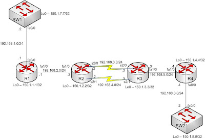
Our lab setup looks like following –

Fig – Network setup for mcast routing
We have configured the network according to the addressing plan given above. We have enabled mcast routing in all routers. All interfaces of the routers are configured in PIM-SPARSE-DENSE mode. IGP (RIPv2) is also configured to get end-to-end reachablity.
For discussion, R2 configuration is given below
ip multicast-routing
int s2/0
ip pim sparse-dense-mode
int s2/0
ip pim sparse-dense-mode
int fa1/0
ip pim sparse-dense-mode
router rip
ver 2
no auto-summary
network 0.0.0.0
Our mcast source is SW1 and receiver is SW2. SW1 will generate mcast traffic for group 224.1.1.1. SW2 will use IGMP to join this group and receive the mcast traffic. For generating traffic we will use Cisco IOS IP SLA. Let’s define our SLA in SW1 first –
ip sla monitor 10
type udpEcho dest-ipaddr 224.1.1.1 dest-port 12345 source-ipaddr 192.168.1.2
timeout 0
frequency 5
ip sla monitor schedule 10 life forever start-time now
Explanation – SLA configuration starts with the command - ip sla monitor <number> ; where ‘number’ is used for referencing our defined traffic generator when we want to run it. Under SLA configuration we will define the type of traffic we want to generate. In our example –
Type of traffic generated – UDP Echo
Destination IP address – 224.1.1.1 (Our group IP address)
Source IP address – 192.168.1.2 (SW1’s fa0/0 interface – from where traffic is
generated)
We have also used two additional parameters for our traffic generator – timeout 0 means the traffic generator will not wait for receiver’s respose. And frequency 5 means that after every 5 seconds traffic will be generated again.
After configuring the SLA operation we need to schedule it so that traffic is generated which is done by using this command – ip sla monitor schedule 10 life forever start-time now. Here, we used the monitor number (10) to reference our SLA operation defined earlier. And two parameters we used – this SLA operation start after we typed the command (start-time now) and it will run indefinitely until we stop it manually (life forever).
So, at this point SW1 is generating mcast traffic for group 224.1.1.1. Now SW2 need to join this group to receive mcast traffic. SW2 can join the group by using the following command –
int fa0/0
ip igmp join-group 224.1.1.1
How we can verify that SW2 is actually receiving the mcast traffic? First we can look at mcast routing table entry in our routers. As there is no RP or BSR router configured our network will run in PIM-DM. We can look at various SPT (Shortest path tree – S,G entry) created for group 224.1.1.1 in the routers.
The (192.168.1.2, 224.1.1.1) entry at router R2
R2#sh ip mroute
IP Multicast Routing Table
(192.168.1.2, 224.1.1.1), 00:03:00/00:02:58, flags: T
Incoming interface: FastEthernet1/0, RPF nbr 192.168.2.1
Outgoing interface list:
Serial2/0, Prune/Sparse-Dense, 00:03:00/00:00:03, A
Serial2/1, Forward/Sparse-Dense, 00:02:43/00:00:00
The (192.168.1.2, 224.1.1.1) entry at router R4
R4#sh ip mroute
IP Multicast Routing Table
(192.168.1.2, 224.1.1.1), 00:04:37/00:02:53, flags: T
Incoming interface: FastEthernet1/0, RPF nbr 192.168.5.3
Outgoing interface list:
FastEthernet0/0, Forward/Sparse-Dense, 00:04:20/00:00:00
From the above two entry we can see the incoming and outgoing interface for our mcast traffic. The (192.168.1.2, 224.1.1.1) entry in R4 has fa0/0 in outgoing interface list, which signifies that there is a receiver for 224.1.1.1 group via R4’s fa0/0 interface. In this case the receiver is SW2. So, this shows that mcast traffic is flowing across the network and receiver is getting the traffic.
We can also verify it by enabling mcast packet debugging. By default, mcast packets are fast-switched. So, if we use the command – debug ip mpacket ; there will be no output. In Cisco routers the only way to debug packet is to disable all the alternate switching paths (Fast-switching, CEF switching etc.). When packets are process switched only we can debug them. To enable process switching we need to type the following command in interface configuration mode – no ip mroute-cache.
R4#conf t
Enter configuration commands, one per line. End with CNTL/Z.
R4(config)#int fa1/0
R4(config-if)#no ip mroute-cache
R4(config-if)#exit
R4(config)#do debug ip mpacket
IP multicast packets debugging is on
R4(config)#
*Mar 1 00:36:45.899: IP(0): s=192.168.1.2 (FastEthernet1/0) d=224.1.1.1 (FastEthernet0/0) id=0, ttl=251, prot=17, len=44(44), mforward
*Mar 1 00:36:50.995: IP(0): s=192.168.1.2 (FastEthernet1/0) d=224.1.1.1 (FastEthernet0/0) id=0, ttl=251, prot=17, len=44(44), mforward
*Mar 1 00:36:55.955: IP(0): s=192.168.1.2 (FastEthernet1/0) d=224.1.1.1 (FastEthernet0/0) id=0, ttl=251, prot=17, len=44(44), mforward
From the debug output we can see that mcast packet from 192.168.1.2 is coming into fa1/0 interface. The destination is group address 224.1.1.1. And the R4 consults it’s mcast routing table and finds only one outgoing interface - fa0/0. So, the traffic is forwarded to that interface.
This is the detail way to generate mcast traffic for a lab setup and verify the operation. There is another easy way to check the mcast routing operation. That is by using mtrace command. This command is like trace command used for unicast path tracing. The command format is –
mtrace src-ip dest-ip grp-ip
By using this command we can trace the reverse path (from destination to source) for a mcast group. And another benefit of this command is that we can use this command form any router in the network as long as we have reachablity to source and destination IP address. This command is very ideal for verifying the mcast traffic path in real networks before feeding the actual mcast traffic into the network.
R3#mtrace 192.168.1.2 192.168.6.2 224.1.1.1
Type escape sequence to abort.
Mtrace from 192.168.1.2 to 192.168.6.2 via group 224.1.1.1
From source (?) to destination (?)
Querying full reverse path...
0 192.168.6.2
-1 192.168.5.4 PIM [192.168.1.0/24]
-2 192.168.5.3 PIM [192.168.1.0/24]
-3 192.168.4.2 PIM [192.168.1.0/24]
-4 192.168.2.1 PIM [192.168.1.0/24]
-5 192.168.1.2
In the above example we try to trace the path for group 224.1.1.1; if SW1 (192.168.1.2) is the source and SW2 (192.168.6.2) is the receiver. The path is traced from the destination to source. If the trace is completed successfully – our network is capable of forwarding mcast traffic. This is another very easy way to test mcast reachablity.
For detail explanation of IP SLA operation and mtrace please look at Cisco IP SLA Configuration guide and Cisco IP Multicast configuration guide.
Next time I will try to talk about mcast load balancing in the context of RPF check and switching paths (process switching, fast switching, CEF). Stay tuned.
For discussion, R2 configuration is given below
ip multicast-routing
int s2/0
ip pim sparse-dense-mode
int s2/0
ip pim sparse-dense-mode
int fa1/0
ip pim sparse-dense-mode
router rip
ver 2
no auto-summary
network 0.0.0.0
Our mcast source is SW1 and receiver is SW2. SW1 will generate mcast traffic for group 224.1.1.1. SW2 will use IGMP to join this group and receive the mcast traffic. For generating traffic we will use Cisco IOS IP SLA. Let’s define our SLA in SW1 first –
ip sla monitor 10
type udpEcho dest-ipaddr 224.1.1.1 dest-port 12345 source-ipaddr 192.168.1.2
timeout 0
frequency 5
ip sla monitor schedule 10 life forever start-time now
Explanation – SLA configuration starts with the command - ip sla monitor <
Type of traffic generated – UDP Echo
Destination IP address – 224.1.1.1 (Our group IP address)
Source IP address – 192.168.1.2 (SW1’s fa0/0 interface – from where traffic is
generated)
We have also used two additional parameters for our traffic generator – timeout 0 means the traffic generator will not wait for receiver’s respose. And frequency 5 means that after every 5 seconds traffic will be generated again.
After configuring the SLA operation we need to schedule it so that traffic is generated which is done by using this command – ip sla monitor schedule 10 life forever start-time now. Here, we used the monitor number (10) to reference our SLA operation defined earlier. And two parameters we used – this SLA operation start after we typed the command (start-time now) and it will run indefinitely until we stop it manually (life forever).
So, at this point SW1 is generating mcast traffic for group 224.1.1.1. Now SW2 need to join this group to receive mcast traffic. SW2 can join the group by using the following command –
ip igmp join-group 224.1.1.1
How we can verify that SW2 is actually receiving the mcast traffic? First we can look at mcast routing table entry in our routers. As there is no RP or BSR router configured our network will run in PIM-DM. We can look at various SPT (Shortest path tree – S,G entry) created for group 224.1.1.1 in the routers.
The (192.168.1.2, 224.1.1.1) entry at router R2
IP Multicast Routing Table
(192.168.1.2, 224.1.1.1), 00:03:00/00:02:58, flags: T
Incoming interface: FastEthernet1/0, RPF nbr 192.168.2.1
Outgoing interface list:
Serial2/0, Prune/Sparse-Dense, 00:03:00/00:00:03, A
Serial2/1, Forward/Sparse-Dense, 00:02:43/00:00:00
The (192.168.1.2, 224.1.1.1) entry at router R4
IP Multicast Routing Table
(192.168.1.2, 224.1.1.1), 00:04:37/00:02:53, flags: T
Incoming interface: FastEthernet1/0, RPF nbr 192.168.5.3
Outgoing interface list:
FastEthernet0/0, Forward/Sparse-Dense, 00:04:20/00:00:00
From the above two entry we can see the incoming and outgoing interface for our mcast traffic. The (192.168.1.2, 224.1.1.1) entry in R4 has fa0/0 in outgoing interface list, which signifies that there is a receiver for 224.1.1.1 group via R4’s fa0/0 interface. In this case the receiver is SW2. So, this shows that mcast traffic is flowing across the network and receiver is getting the traffic.
We can also verify it by enabling mcast packet debugging. By default, mcast packets are fast-switched. So, if we use the command – debug ip mpacket ; there will be no output. In Cisco routers the only way to debug packet is to disable all the alternate switching paths (Fast-switching, CEF switching etc.). When packets are process switched only we can debug them. To enable process switching we need to type the following command in interface configuration mode – no ip mroute-cache.
Enter configuration commands, one per line. End with CNTL/Z.
R4(config)#int fa1/0
R4(config-if)#no ip mroute-cache
R4(config-if)#exit
R4(config)#do debug ip mpacket
IP multicast packets debugging is on
R4(config)#
*Mar 1 00:36:45.899: IP(0): s=192.168.1.2 (FastEthernet1/0) d=224.1.1.1 (FastEthernet0/0) id=0, ttl=251, prot=17, len=44(44), mforward
*Mar 1 00:36:50.995: IP(0): s=192.168.1.2 (FastEthernet1/0) d=224.1.1.1 (FastEthernet0/0) id=0, ttl=251, prot=17, len=44(44), mforward
*Mar 1 00:36:55.955: IP(0): s=192.168.1.2 (FastEthernet1/0) d=224.1.1.1 (FastEthernet0/0) id=0, ttl=251, prot=17, len=44(44), mforward
From the debug output we can see that mcast packet from 192.168.1.2 is coming into fa1/0 interface. The destination is group address 224.1.1.1. And the R4 consults it’s mcast routing table and finds only one outgoing interface - fa0/0. So, the traffic is forwarded to that interface.
This is the detail way to generate mcast traffic for a lab setup and verify the operation. There is another easy way to check the mcast routing operation. That is by using mtrace command. This command is like trace command used for unicast path tracing. The command format is –
By using this command we can trace the reverse path (from destination to source) for a mcast group. And another benefit of this command is that we can use this command form any router in the network as long as we have reachablity to source and destination IP address. This command is very ideal for verifying the mcast traffic path in real networks before feeding the actual mcast traffic into the network.
Type escape sequence to abort.
Mtrace from 192.168.1.2 to 192.168.6.2 via group 224.1.1.1
From source (?) to destination (?)
Querying full reverse path...
0 192.168.6.2
-1 192.168.5.4 PIM [192.168.1.0/24]
-2 192.168.5.3 PIM [192.168.1.0/24]
-3 192.168.4.2 PIM [192.168.1.0/24]
-4 192.168.2.1 PIM [192.168.1.0/24]
-5 192.168.1.2
In the above example we try to trace the path for group 224.1.1.1; if SW1 (192.168.1.2) is the source and SW2 (192.168.6.2) is the receiver. The path is traced from the destination to source. If the trace is completed successfully – our network is capable of forwarding mcast traffic. This is another very easy way to test mcast reachablity.
Next time I will try to talk about mcast load balancing in the context of RPF check and switching paths (process switching, fast switching, CEF). Stay tuned.

Gr8 man. keep it up. :D
ReplyDeleteYour best buddy, Liton